
Since I got my Zafira B with power folding mirrors option, I was annoyed by the fact, that the mirrors would fold/extend only when the key was in the ignition. Once it was removed and one of the doors opened (or if you operated the mirrors during engine start-up), the current to the mirror motors would get cut and you ended up with half-folded/extended mirrors. Hey, I bet there must be a way to fix this annoyance, right?
Once I opened the schematics in TIS2000, it was obvious, that the driver door switch was powered through ignition voltage (which gets cut off after removing the key from ignition and opening the door), even though there is also battery voltage present on the connector to the switch used for the mirror folding motors.

Ignition voltage is wired through 0.5mm black wire to pin 26 and connects to all window lifter switches S115.1 – S115.4, child security switch S115.5, illumination diodes S115.6, outside mirror adjust switches S115.6 and finally outside mirror fold/unfold switch S115.9. Battery positive voltage is wired through 0.75mm red wire to pin 13, which connects via a double relay to mirror folding motors via pins 6&22 (fold) or 7&23 (extend).
First idea was to just remove pin on position 13 (ignition voltage) from the switch unit connector and replace it with a new wire run from battery voltage wire connected to pin 26. This idea was abandoned after I realized this would mean that the battery voltage would be provided to window lifter switches, mirror adjustment switches, and illumination as well, and would enable to operate the windows after (dead)locking the car and consume current by illumination LEDs (I believe that since this battery voltage comes from REC via fuse FR26, it gets disconnected after approx. 30 minutes, but still). Therefore I decided to modify the voltage feed on the PCB instead – cut the ignition voltage coming from pin 26 before the fold button logic block and feed it from the battery voltage coming on pin 13.

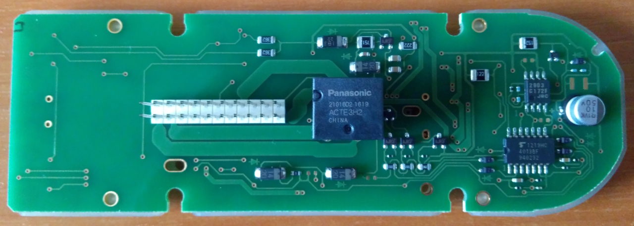
Here is a detailed view of the printed circuit board after disassembling the switch unit. Bottom side hosts ACTE dual relay (Panasonic ACTE3H2) for flipping GND/+12V on the two wires to the mirror folding motors for fold/extend function and other circuitry (resistors for illumination diodes, capacitor for timing the folding process etc.).
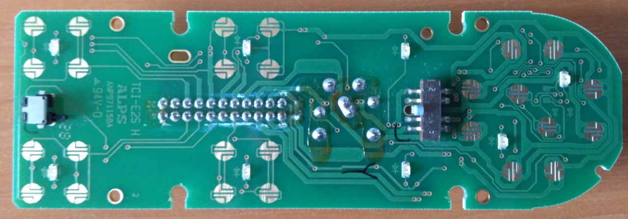
On the top side there is child security switch and mirror selector switch, illumination diodes, and switching contacts for window lifters and mirror operation.
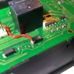
After studying the PCB layout and tracing the lines from the connector I determined the applicable point where to cut the ignition voltage and solder the battery voltage to feed the folding circuitry. You cut the trace after the junction towards the diode as outlined with the green dotted line (make sure the trace towards the left diode stays intact) and solder new wire from pin 13 onto the left contact of the right diode (red solid line).

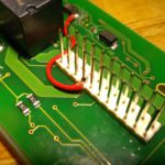
Following are the actual pictures of my modification (I do not own a decent micro soldering station so the solder points are a bit rough) and a video showing the driver switch operation with enabled folding/extending of the mirrors even after the ignition voltage is turned off.

Hi mate,Ive just fitted zaf power folds but would be interested in your remote module,are you due to make any more and how much thanks Dave